Friday, May 19, 2017

Configuring SSL Decryption Policy on a Palo Alto Networks Firewall

Decryption

Palo Alto Networks firewalls provide the capability to decrypt and inspect traffic for visibility, control, and granular security. Decryption on a Palo Alto Networks firewall includes the capability to enforce Security policies on encrypted traffic, where otherwise the encrypted traffic might not be blocked and shaped according to your configured security settings. Use decryption on a firewall to prevent malicious content from entering your network or sensitive content from leaving your network concealed as encrypted traffic. Enabling decryption on a Palo Alto Networks firewall can include preparing the keys and certificates required for decryption, creating a decryption policy, and configuring decryption port mirroring.

Traffic that has been encrypted using the protocols SSL and SSH can be decrypted to ensure that these protocols are being used for the intended purposes only, and not to conceal unwanted activity or malicious content.


SSL Forward Proxy

Decryption of outbound SSL traffic is commonly implemented and takes the form of SSL Forward Proxy, which features the firewall as an intermediate communication node. This deployment commonly referred to as a "Man in the Middle."

Note that SSL Forward Proxy replaces the original certificate from the final destination with ne signed by a different key that is then delivered to the client.

A developer of a solution using SSL decryption can take extra programmatic steps to interrogate the certificate received at the client for specific characteristics present in the original certificate. When these characteristics aren't fund the author often assumes that a Decryption process is in the middle of the conversation and may take action to prevent full functionality considering this presence of a security risk. These products typically are not fully functional in a decrypting environment and must be added as exceptions to Decryption policies.

More information can be found on this link.


The PAN firewall can acts as a proxy between a client (TRUST zone) and an HTTPS website (UNTRUST zone or Internet) and decrypt inbound/outbound SSL traffic in order to apply inspection policies. To configure Outbound SSL Decryption, you need to generate first a self-signed certificate from the PAN firewall by going to Device > Certificate Management > Certificates > Generate.


Type a name under Certificate Name (PAN-SSL-CERT) > type a name under Common Name (Lagura) > check Certificate Authority > leave the default settings under Cryptographic Settings.


Under Certificate Attributes > click Add >Country > type and search for your country (SG in my case) > add and fill other Certificate Attributes as needed >click Generate.


You need to modify the certificate by clicking on the Name of the certificate (PAN-SSL-CERT) > check Forward Trust Certificate, Forward Untrust Certificate and Trusted Root CA > click OK.


You can export the PAN certificate and install it on the PC web browser by clicking on the Name of the certificate and click Export. Leave the File Format of Base64 Encoded Certificate (PEM) > check Export private key > type a passphrase twice to confirm > click OK.


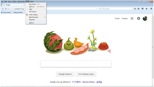
Go to the folder where the PEM certificate got downloaded (Downloads folder on my Windows 7). Manually install the certificate (can also automate via GPO) on the web browser (Mozilla Firefox) by going to Tools > Options


Go to Advanced > Certificates > View Certificates.


Under Authorities > click Import.


Go to Downloads folder and choose the created PEM certificate > click Open > click Trust the CA to identify websites > click OK.


You can view the certificate under Authorities tab > click on the installed PEM certificate > View.


Just like in creating a Security or NAT policy, configure a Decryption policy from left to right. Under General > type the Name of the Decryption rule.


Under Source tab > choose TRUST-L3 under Source Zone > choose TRUST-ZONE-USERS (which is 172.17.101.0/24) under Source Address.


Under Destination tab > choose UNTRUST-L3 under Destination Zone > leave Any under Destination Address (which is Any address on the UNTRUST zone/Internet).


Under URL Category > click Add > type and search: social-networking (click social-networking) > type and search: web-based-email (click web-based-email)


Under Options tab > select Decrypt under Action > leave the default of SSL Forward Proxy under Type and None under Decryption Profile > click OK.


You also need a Security rule to decrypt and allow the HTTPS application. You can create An Application object or use the pre-defined Application objects by going to Objects > Applications.


In this example, the Security rule will decrypt and inspect Facebook and Outlook Web Access which are both HTTPS websites. You can type and search for a specific Application such as facebook > click facebook-base which is the general web browsing on Facebook. You can click on a specific Application to view more details such as the Description, Standard Ports, etc. This feature truly makes the PAN firewall a “next-generation” firewall, which means it doesn’t only filter traditional TCP and UDP ports (Layer 4) but on the Application layer (Layer 7) as well.


You can also add another Security rule to decrypt and inspect webmail such as Outlook Web Access (OWA).


To create a new Security rule, go to Policies > Security > Add.


Under General tab > type the Name of the Security rule (OUTBOUND-SSL-DECRYPT) > optionally type the Description.


Under Source tab > choose TRUST-L3 under Source Zone > choose TRUST-ZONE-USERS under Source Address.


Under Destination tab > choose UNTRUST-L3 under Destination Zone > leave the default of Any under Destination Address.


Under Application tab > type and search: facebook > click facebook-base (only decrypt and inspect general Facebook web browsing).


Add web-browsing, ssl and dns Application to ensure HTTPS web browsing will work.


Leave the default settings of Allow and Log at Session End under Actions.


Click OK and Commit.


I've made some tests by going to my Facebook page and opening Outlook. To verify the Decryption and Security rules are working, go to Monitor > Logs > Traffic. Notice there's an Application log for facebook-base and ssl for Outlook web (public IP 111.221.29.254).


Friday, May 12, 2017

Configuring Syslog, SNMP and NetFlow on a Palo Alto Networks Firewall

Firewall Log Forwarding

Using an external service to monitor the firewall enables you to receive alerts for important events, archived monitored information on systems with dedicated long-term storage, and integrate with third-party security monitoring tools.

Log storage on Palo Alto Networks firewalls is strictly allocated between different log and other storage types to ensure that no particular log is overrun by another. This allocation is user controlled.

Each storage area typically acts as circular logs in that, when filled, new entries will overwrite old ones. Space is cleared in blocks and messages added to the System log.

Before you can use Panorama or external systems to monitor the firewall, you must configure the firewall to forward its logs. Before forwarding to external services, the firewall automatically converts the logs to the necessary format: syslog messages, SNMP traps, or email notifications. Before you start this procedure, ensure that Panorama or the external server that will receive the log data already is set up.

External forwarding supports the following types of destinations:

1. SNMP traps
2. Syslog
3. Email
4. Panorama

There are two main methods to forward log events, depending on the log message type. Log events destined for the System, Config, and HIP Match log are redirected using Device > Log Settings to choose event destination (s) for specific event types.

Event normally written to the Traffic, Threat, and WildFire Submission logs are routed via a Log Forwarding profile.

Log forwarding profiles are attached to individual firewall Security policies to enable forwarding of the events associated with the processing of the specific policy. This granularity allows administrators specific control of forwarding and the potential of different forwarding for policies of differing importance.

All forwarded events are delivered as they are generated on the firewall.

A complete discussion of log forwarding configuration can be found on this link.


Syslog

I've used the free 3CDaemon Syslog server for my Palo Alto lab.


To configure a PAN firewall to send logs to an external Syslog server, go to Device > Server Profiles > Syslog > Add.


Type a Name for the Syslog Server Profile (SYSLOG-PROF) > under Servers tab click Add > type a Name for the server > type the IP address (or FQDN) under Syslog Server (10.67.78.3) > leave the default settings for Transport, Port and Protocol columns > choose LOG_LOCAL6 (Informational) under Facility > click OK. 

As a best practice, network devices should be enabled for syslog facility level 6 (covers levels 0-6) under normal operations. Level 7 is normally used for console troubleshooting (debug) only.


To enable and forward Traffic and Threat logs to a Syslog server (or to Panorama server), go to Objects > Log Forwarding > Add.


Type a Name for the Log Forwarding Profile (LAB-FWD-PROF) > under Traffic Settings click None under Syslog column > choose the syslog profile created earlier (SYSLOG-PROF).


Choose the same syslog profile (SYSLOG-PROF) under the Threat and WildFire Settings that you selected. Click OK.


Apply the Log Forwarding Profile created on a Security rule by going to Policies > Security.


I’ve enabled the Log Forwarding profile on Security rule 1 (ALLOW-PING) under Actions tab > click Log at Session Start > choose LAB-FWD-PROF under Log Forwarding.


I've also enabled Log Forwarding on Security rule 2 (ALLOW-INTERNET-ACCESS), which is my PAT rule from TRUST zone to UNTRUST or Internet zone. Click Commit to apply the changes.


As soon as the changes were applied, the PAN firewall started sending syslogs. Notice the traffic logs hit the rules such as the USER-INTERNET-ACCESS and ALLOW-PING.


SNMP


To configure SNMP on a PAN firewall, go to Device > Setup > Operations > click SNMP Setup under Miscellaneous.


Type the Physical Location and Contact > choose V3 under Version > under Name click Add to create the SNMPv3 view profile.


Type a Name under View (LAB-VIEW) > type the OID string 1.3.6.1.4.1.25461.2.3.12 (for PA-200) > choose include under Options > type 0x80 under Mask > click OK.


Click Add under Users to add the SNMPv3 user (panfw200) > choose LAB-VIEW under View > type twice the Auth Password > type twice the Priv Password > click OK twice. The PAN OS 7 (as of this writing) only supports SHA-1 (Authentication) and AES128 (Privacy) for SNMPv3.


To enable SNMP on the MGMT interface, go to Device > Setup > Management Interface Settings > click Edit (gear icon).


Click SNMP under Services > click OK > Commit.
 

I've used ManageEngine OpManager (v12.2), which is a free SNMP and NetFlow monitoring tool (up to 10 devices). You just need to allow the OpManager program on your personal firewall.


Just follow the steps on the installation wizard.


Choose Free Edition in order to monitor up to 10 devices and the license will never expire. This is good for a lab environment.


You can optionally choose other WebServer and NetFlow ports. I've just changed the WebServer port to 8080 (since I’m running IIS on port 80) and left the NetFlow flow in default.


You can optionally fill up your personal information.


Wait until the installation completes.


Choose Standalone > click Next.


Choose POSTGRESQL > click Next.
 

There's a warning saying that you need to allow OpManager to run on any installed Anti-virus and personal firewall settings.


Click Finish and OpManager (web client) will launch automatically (in a web browser).


It tool several minutes to complete the installation. You can login using the default username and password of admin/admin.


Press Esc to exit the Youtube tour (opened in a new tab).


Go to Discovery > Add Device > type the Device IP Address of the PAN firewall (10.68.78.91/24).


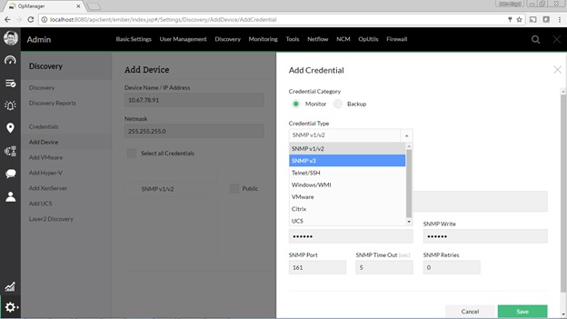
Click Add Credential on the right-hand side to configure SNMPv3 > choose Monitor under Credential Category > choose SNMP v3 under Credential Type.


Type a Name of device (PA-200-LAB) > optionally type a Description > type the SNMPv3 User Name (panfw200).


Choose SHA (SHA-1) under Authentication Protocol > type the Authentication password (configured the same on the PAN firewall).


Choose AES-128 under Encryption Protocol > type the Encryption (Privacy) password (configured the same on the PAN firewall).


Leave the default SNMP Port and timers in default > click Save.


The PA-200-LAB Credential will appear under Select all Credentials > select PA-200-LAB > click OK.


The OpManager wasn't able to detect the PAN firewall even though the SNMP Protocol Test Credential have Passed. I tried changing the OID to 1.3.6.1.6 and 1.3.6.1 (and changed Mask to 0xf0) but still SNMPv3 failed.


I tried configuring the SNMPv2c SNMP Community String (panfw200) instead.


The PAN firewall Status showed Trouble since its ethernet1/3 and ethernet1/4 are both down.


Notice there are no interface bandwidth graphs since you need to configure NetFlow in order to view interface traffic and top talkers on the network.


NetFlow

To configure NetFlow on a PAN firewall, go to Device > Server Profiles > NetFlow > Add.


Type a Name of the NetFlow Profile (NETFLOW-PROF) > click Add under Name > type a Name for the server (SERVER-1) > type the NetFlow Server IP address (10.67.78.3) > change the port to 9996 (used by OpManager) > click OK.


Apply the NetFlow Profile on the PAN firewall interfaces that you want to monitor. You usually enable NetFlow on the ingress (ethernet1/2 or TRUST-L3) and egress (ethernet1/1 or UNTRUST-L3) interfaces. Go to Network > Interfaces.


Click on the interface (ethernet1/1) > choose the NetFlow profile created earlier (NETFLOW-PROF) under NetFlow Profile > click OK. Configure the same on the ingress interfaces (ethernet1/2). Click Commit afterwards.


The interface bandwidths graphs were generated after NetFlow (see Version 9 under Flow Analysis) was enabled on the ingress (ethernet1/2) and egress (ethernet1/1) interfaces on the PAN firewall.


These are the bandwidth graphs for the ingress (ethernet1/2) interface.


To view top talkers and top applications, go to Dashboard (gauge icon on the left-hand side) > click NetFlow column.